Through the use of COMSOL software, Unictron has built simulation capability for piezoelectric elements and piezoelectric modules in recent years. The simulation technology uses mainly the principle of finite element method (FEM) to perform analysis and simulation. Finite Element Method (FEM) is a systematic method used for numerically solving differential equations or integral equations, thus it can solve for a variety of complex geometric shapes or different boundary conditions. By dividing a large system into smaller, simpler parts, i.e. finite elements, generating mesh, followed by optimization/post-processing, simulation, modularization and other related functions, it can be used effectively to explain multiple coupling or multiple physical phenomena. Multi-physics coupling analysis can be used to simulate optics, structure, fluid, heat, chemistry, acoustics, etc. with applications in the fields of engineering, building, aerospace, semiconductor, medicine… etc.
In the simulation process, the first step is to perform 2D/3D modeling and to define the parameters in integral formula; the second step is to set material parameters of each part, such as density, Young`s modulus, Poisson`s ratio, thermal conductivity, etc. The meshing step is followed afterwards. By meshing, it means to divide the model structure into many small units. Tetrahedral meshes are typically used for segmentation in 3D models. When the model is divided into many small meshes, there are various mesh points at the end points which are also called nodes. The finite Element Method (FEM) is used to calculate the value at each node. The final step is to set the required expressions that need to be solved, such as frequency domain, steady state, time dependence, linear buckling, etc., to complete the simulation process
Through the above simulation process, data such as the resonant frequency, resonant mode, stress analysis, amplitude analysis…etc. for the piezoelectric element or piezoelectric module can be obtained. Based on the results of the analysis, optimization adjustments can be further proceeded, such as: modification of geometric shapes, materials, mechanisms, etc.
Advantages of Simulation technology are as following:
- Predict product performance state under different conditions
- Design parameter can be quickly and conveniently adjusted according to simulation results
- Reduce repetitive trial and error experimental process, shorten product development time, reduce greatly the material, manpower and time costs
- Optimal design analysis and maximizing product effectiveness can be automatically performed by the software
- In addition to new product development, it can also be used to optimize the existing products.
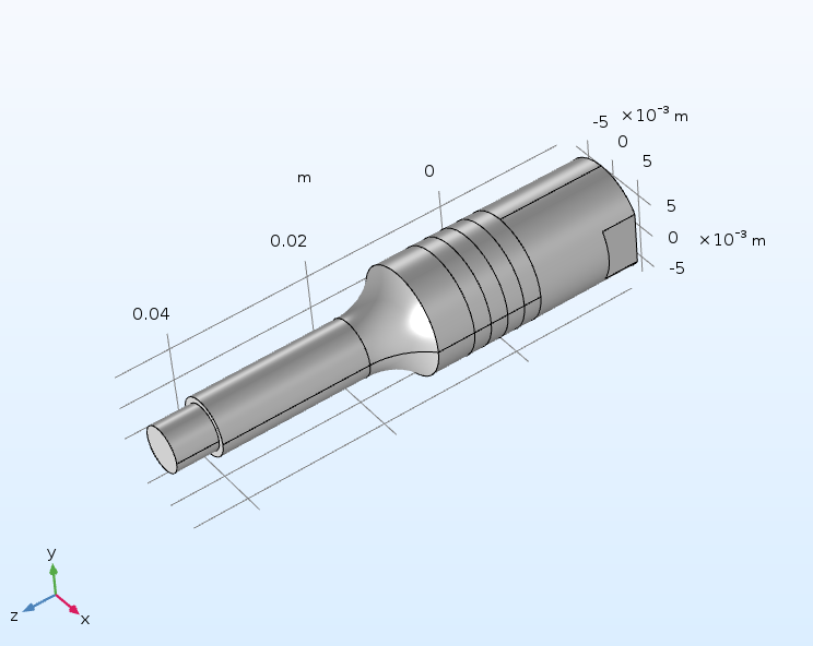
Below is an example using Bolt Clamped Langevin Transducer to illustrate the process and results of the simulation analysis:,
- Fig. 1. 3D model building.
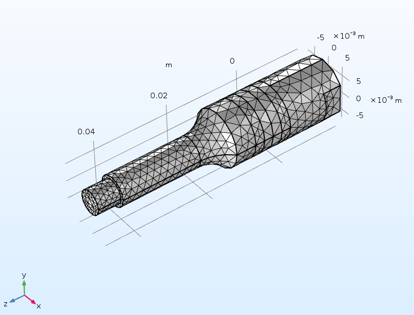
- Fig. 2. Creation of a mesh after setting the material parameters of each component.
- Fig. 3. Mode analysis in the simulation results uder the Z-axis vibration mode.
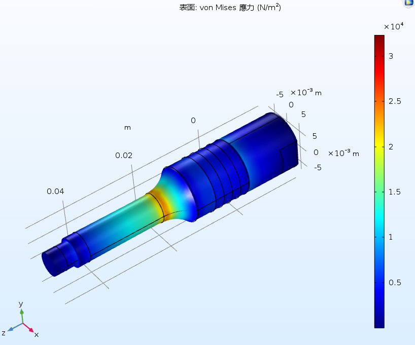
- Fig. 4. Stress analysis in the simulation results. Stress distribution in the Bolt Clamped Langevin transducer structure can be analyzed.
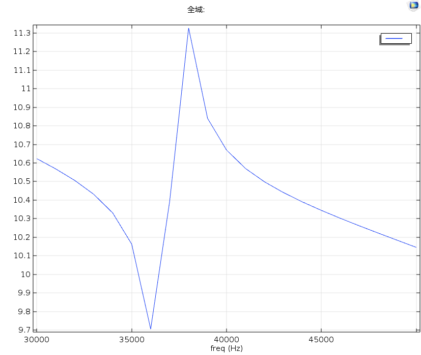
- Fig. 5. Frequency domain analysis in the simulation results. The resonant frequency is at 36 kHz for the Bolt Clamped Langevin transducer.
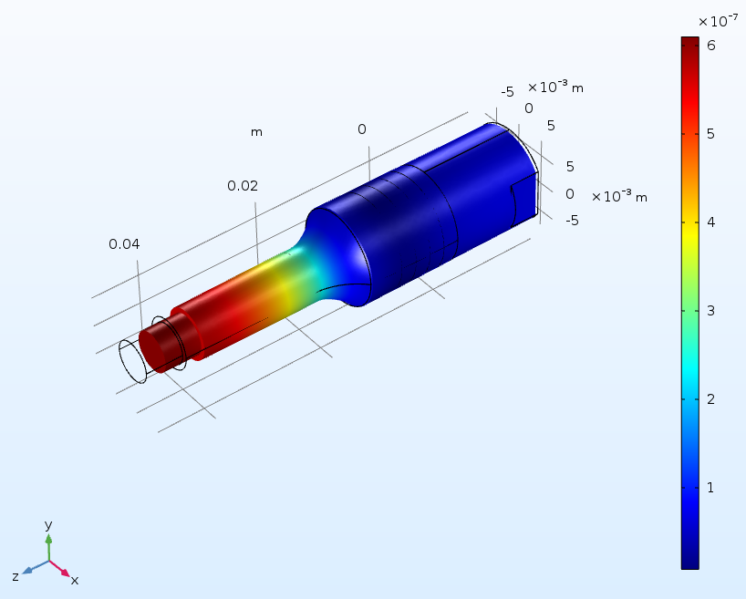
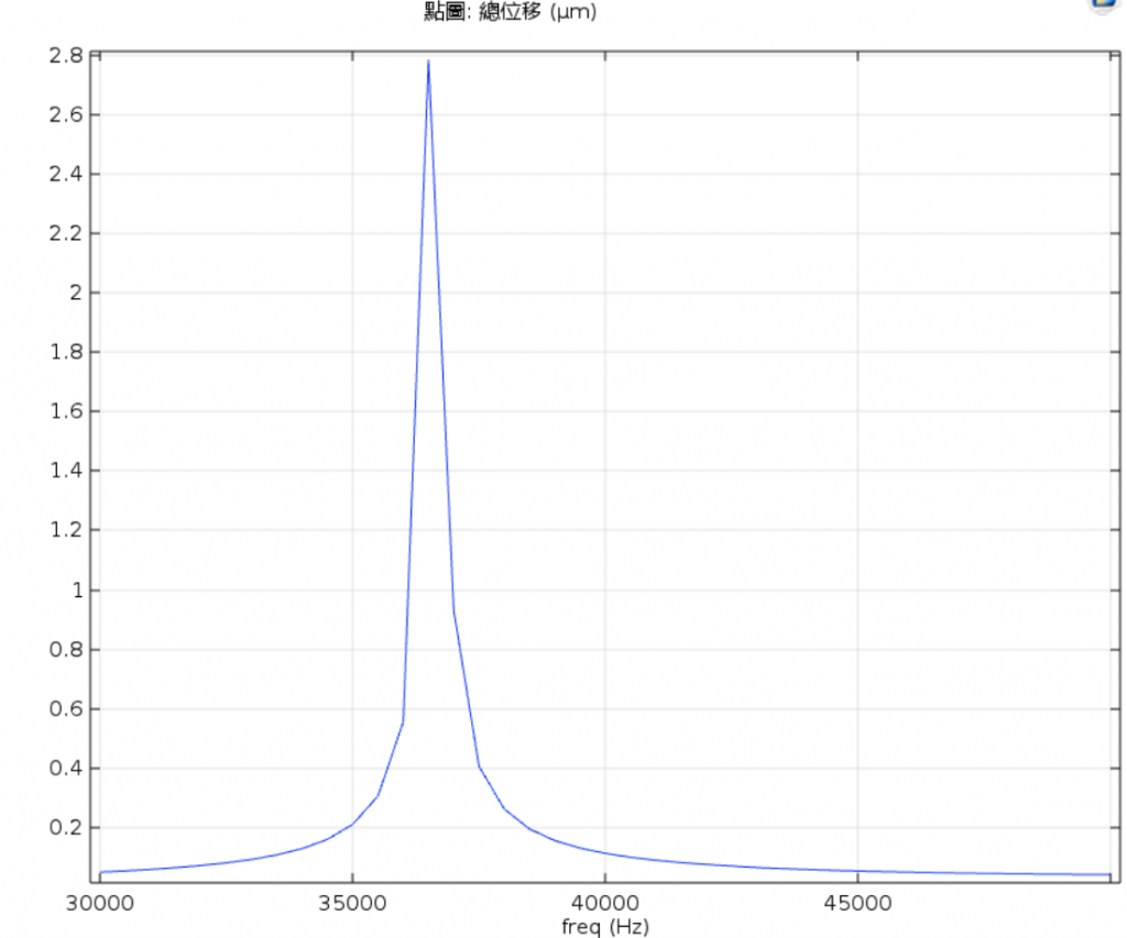
- Fig.6. Vibrational displacement analysis in the simulation results. The displacement is 2.78μm for the Bolt Clamped Langevin transducer driving at 36 kHz / 10Vpp voltage.
Please refer to the figures below: