
Diaphragm gas flow meter vs Ultrasonic gas flow meter:
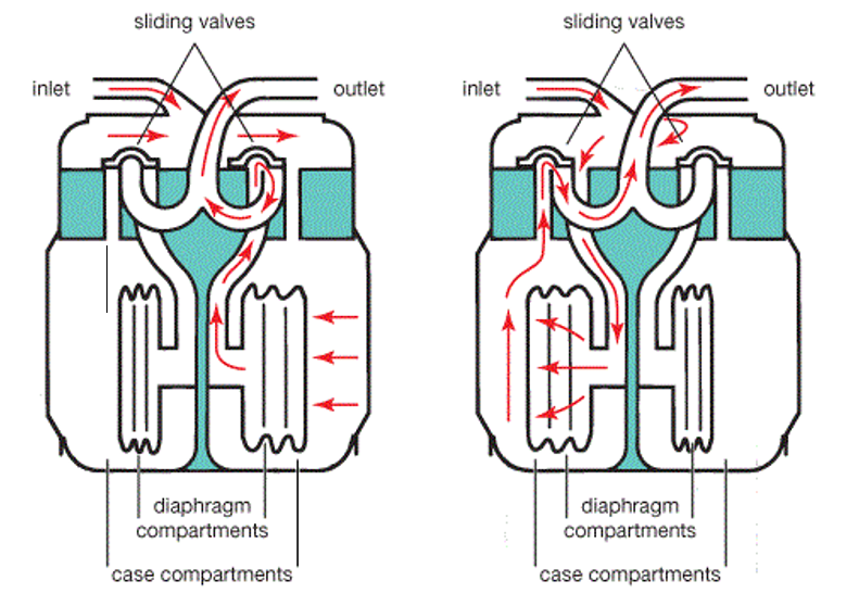
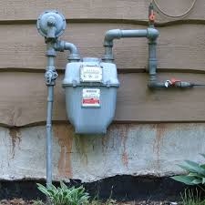
The traditional residential natural gas flow meter is the mechanical diaphragm gas flow meter, as shown the figure below.
Because the operation of the diaphragm gas flow meter is by means of the diaphragm volume expansion and deflation, the slide valve is likely to deteriorate resulting in gas leakage. The greater the gas leakage, the higher measurement error of the diaphragm volumetric flow meter.
Owning to the reason above, people in the industry of natural gas flow meters have actively investigated more accurate and robust method for natural gas flow measurement for decades. Ultrasonic gas flow meter is one of the most promising solutions. It is characterized by no mechanical reciprocating movements, suitable for detecting a variety of different types of gas mixtures, compact size, light weight, high accuracy, and no pressure loss in the pipeline. In recent years, some companies in Europe, the United States, Japan, and fast-growing China have all been aggressively developing ultrasonic natural gas flow meters.
With the well-established internet network system, the smart gas metering has been developed, composed of three main components: WAN, U-Bus Air networks, and Ultrasonic gas flow meters. The ultrasonic gas flow meter is provided with function of IoT which can acquire the residential gas consumption in time transmitting the data through U-Bus Air networks, such as LAN or NB-IoT to WAN. The smart gas metering system has the benefits of: manage the gas consumption in real time, gas leak detection, fire alarm, on-line payment, remote control and monitor.
Features of ultrasonic natural gas flow meter:
- High precision, as precise as ≤ 0.1%
- Durable and high reliability
- No pressure loss in the pipeline during measurement
- High turndown ratio
- Ability to observe instantaneous and cumulative flow
- Ability for bi-directional flow measurement
- Because of no moving parts, there is almost no need for maintenance, which greatly reduces costs for maintenance
- Integral performance diagnostic can be performed online
Principle of ultrasonic gas meter:
The measurement method of the ultrasonic gas flow meter is by means of the difference time of flight (DToF) for ultrasound propagating in upstream of the gas pipeline and downstream to calculate the gas velocity, and then multiply the gas velocity by the cross-sectional area of the pipeline to get the gas flow rate. When the ultrasound travels in the same direction along with the gas, its propagating speed will be faster, otherwise it will be slower.
We can use the DToF of propagating ultrasound to calculate the gas flow velocity and gas flow rate in the pipeline.
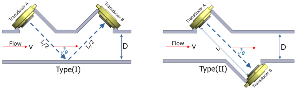
The practical way is to install a pair of ultrasonic air transducers (which can be reflective Type (I) or direct Type (II)) on the upstream and downstream positions of the pipeline channel respectively, as shown in the figure below. The ultrasound propagates from the upstream transducer A to the downstream transducer B in a shorter time (Tdown), and propagating from the downstream transducer B to the upstream transducer A in a longer time (Tup). We can get the gas velocity in the pipeline channel by measuring the propagation time (Tdown and Tup), calculating its time difference, then multiply the known pipeline cross-sectional area to get the flow rate value, as shown below:
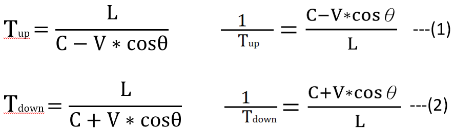
Equation (1) + equation (2) obtained,

Equation (1) – equation (2) obtained,

From the result of the equation (3), it can be known that the gas velocity V has nothing to do with the sound velocity C of gas. The gas velocity V is multiplied by the known pipeline cross-sectional area A to obtain the gas flow rate.
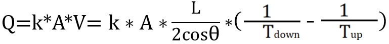
V : gas velocity
C : speed of sound
Tup : Ultrasound propagating time from transducer B to A
Tdown : Ultrasound propagating time from transducer A to B
A : cross-sectional area of the pipeline
Q : gas flow rate
K : correction coefficient
Measurement system for the development of the ultrasonic gas flow meter:
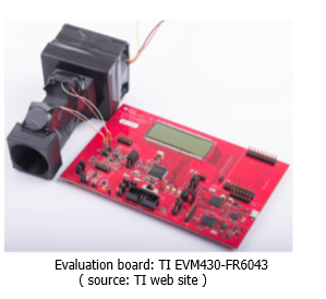
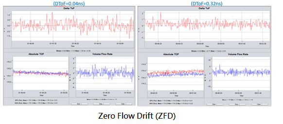
Ultrasonic gas meters require a high-precision signal measurement system to capture the signal and calculate the flow rate. The test kit includes a pair of ultrasonic air transducers setting up in the flow channel and a test circuit. There are some public versions of the test circuit suitable for detecting the ultrasonic gas flow rate can be selected. For example, TI EVM430-FR6043, as shown in the figure below.
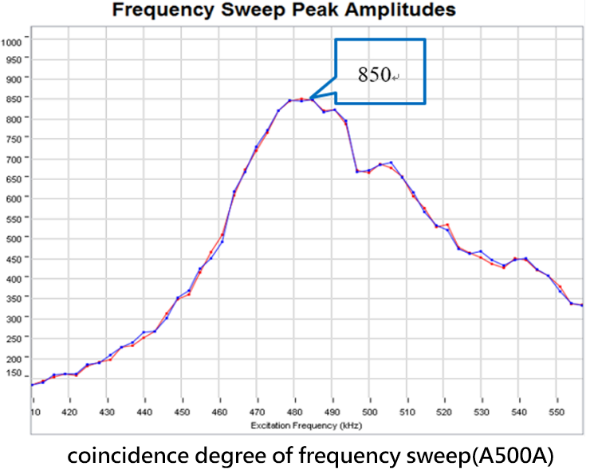
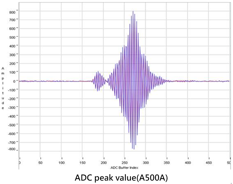
The measurement accuracy of the EVM430-FR6043 can reach ±250 pico seconds (ps,10-12 seconds), which can help us accurately measure the important performance parameters of the gas flow meter, such as frequency sweep, ADC value, Zero Flow Drift (ZFD), etc. The following pictures are the testing results using above test kits provided with the ultrasonic transducers A500A invented by Unictron Corp., working frequency is around 500 kHz.
Industrial Standard for Ultrasonic Natural Gas Flow Meter:
Because the ultrasonic gas flow meter has significant benefits, some countries like the United States and Japan have actually installed it in households for a decade, defined their industrial standards, including working conditions, technical requirements, test methods, and test specifications, etc., such as American National Standards (AGA-9) and Japanese National Standards (JIS B8571). Chinese government also has drafted the national standard specification (JJG-0577.2) for the “Residential Ultrasonic Gas Meter” recently, and it is expected to be implemented in 2021.10.1.
- American National Standard (AGA-9)
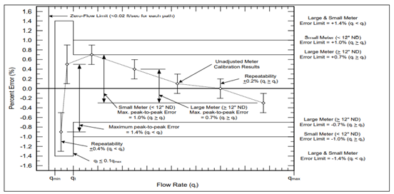
qi : flow rate (m3/h)
qt : transition flow rate
qmin : minimum flow rate
qmax : maximum flow rate
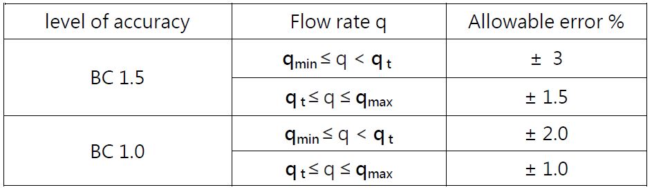
- Japanese National Standard (JIS B8571)
Maximum allowable error of ultrasonic gas meter
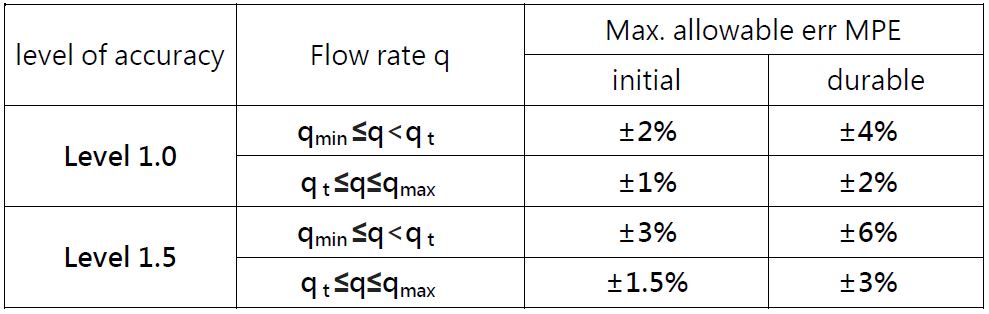
- C hinese National Standard (GBT39841)
Chinese National Standard (GBT39841)
Monitoring and diagnosis of ultrasonic gas flow meter:
In addition to the characteristics of high accuracy and almost no maintenance required, one of the advantages of ultrasonic gas flow meter is the ability to perform the integral diagnosis online, so that we can know the problems instantly, and predict the possible impending failures. Generally, the common parameters used in diagnosis are as follows.
Gain
Modern circuit for detecting ultrasound signal has automatic gain control on all received channels, so that the signal strength can be kept at a certain value constantly. If the gain is found to increase, it means that the signal is weakening, which may be caused by deterioration, surface contamination of the ultrasonic transducers, or some residual liquid in the pipeline.
Signal Quality
Ideally, all signal pulses sent by the transmitter of the ultrasonic transducer will be captured by the receiver transducer. But sometimes the signal is distorted, too weak, or the received pulse does not meet certain standards. When this happens, the electronic circuit will eliminate these accidental bad quality signals. Once too many pulses are eliminated, it will affect the measurement result of the flow meter. There are many logical explanations for this problems. In addition to the excessive gas flow rates, contamination on the transducer surface and excessive external ultrasonic noise are common factors.
Signal-to-Noise Ratio
Not only does each transducer receive signals from the transmitting transducer, but also any noise signals from external sources. Increased noise level will reduce the signal-to-noise ratio, and affect the measurement results. Excessive noise will “overwhelm” the signals, and cause the meter to fail. The main cause of noise is that the frequency of the external signals is too close to the frequency transmitted from the transducer itself. Besides, poor grounding and electrical connection between electronic equipment and transducers, external electromagnetic interference, transducer contamination, pipelines vibration, etc., may all be the sources of noise.
Velocity Profile
The flow velocity of the gas inside the pipeline will be distributed in a curve, the closer to the center of the pipeline, the faster the flow velocity. Generally speaking, the rougher the inner wall of the pipeline, the more “sharp” the flow velocity curve. If there is contamination or foreign matter inside the pipeline, the flow velocity distribution curve we detected will change significantly.
Speed of Sound
Because the calculation of the gas flow rate needs to use the accurate measurement value of the transit time, if the error of the measurement value is large, it will affect the flow measurement result significantly, according to equation (4). Therefore it is important to regularly verify the measured value of the transit time according to equation (3), compared with the sound speed.