Pillar chip antennas technology
 Keywords: Chip antenna, Pillar, WiFi, Router, Switch, Bluetooth, TWS, True wireless stereo, Earphone, Ear bud
 Keywords: Chip antenna, Pillar, WiFi, Router, Switch, Bluetooth, TWS, True wireless stereo, Earphone, Ear bud
Ground clearance and PCB dimensions are no longer a concern
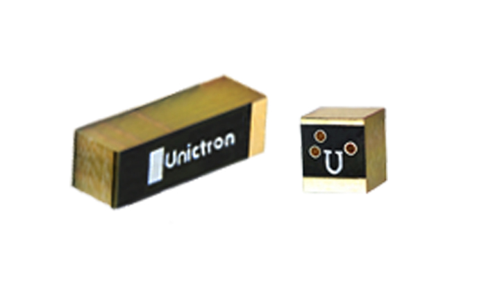
Unictron, a designer and manufacturer of world-class miniature chip antennas, introduced an innovative new product called pillar antenna. Pillar antennas are patented SMD type chip antennas that don’t require much of a ground clearance area and the performance is independent of the dimensions of the ground plane of the circuit board.
Wearable devices normally have limited space and a challenging installation environment for the antenna engineers to design a satisfactory antenna to meet the performance requirements of the devices. Miniature chip antennas installed on small-sized circuit boards may often result in rather poor performance, such as occasional lags when listening to music, or difficulty in connecting to a Wi-Fi network. Furthermore, regular antennas made from FPC or monopole chip antennas show large frequency shifts when the device is worn on a human body. Such frequency shift caused by the change of environment surrounding the antenna may significantly degenerate the signal receiving quality of the antenna.
In general, there are two approaches to minimize the frequency shift of antennas so that the wearable devices can achieve higher RF connection capability:
1. Use loop-type antennas whose near field reactance is dominated by magnetic field, such as Unictron’s TELA antennas; or
2. Use Unictron’s patented Pillar antennas which can have vertical polarization and don’t require ground clearance, therefore antenna performance is not as sensitive to the surrounding environment.
According to the general principles of antenna design, a ground plane on a printed circuit board (PCB) not only behaves as a metal layer to reflect RF waves but also allows the antenna to induce image current on the ground plane which may degenerate the performance of the antenna. Therefore, in designing an antenna, no metal layers are allowed above or below the antenna, which is so called the ground clearance (area without metal). However, the existence of a ground plane between antenna and human body can minimize the influence of human body on the impedance of the antenna, therefore minimize or eliminate the frequency shift and deterioration of antenna performance.
It is always a challenge for an antenna designer of wearable devices to design an antenna with a ground plane underneath the antenna to minimize the influence of the human body on antenna performance and in the meantime also avoid the negative impact of image current which may be induced on the ground plane. Unictron’s antenna developing team has been devoted to resolve this challenge and come out with a patented chip antenna called Pillar Antenna. Unictron’s first pillar antenna is the CW337. This high performance chip antenna works at 2.4GHz ISM band to support all miniature portable devices, such as: ear phone, for Bluetooth and Wi-Fi connections. Unictron’s CW337 pillar chip antennas offer the best from both worlds: a miniature chip antenna on the ground plane for wearable devices with little negative impact of image current and frequency shift.
The pictures below show several versions of installation locations of CW337 on a circuit board. The green color represents the metal layer while the blue color represents the area without the metal layer. The yellow area is the metal pad for antenna installation. Some space around the installation pad of the antenna is needed on the top metal layer to separate the antenna from the ground plane.
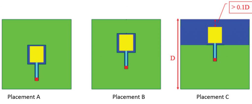
Please note that the above pictures represent a top view of the PCB. When implementing the CW337, it is always recommended to have a full metal layer on the bottom side of the PCB to reduce the influence of the human body on antenna performance.
Antenna installation
Since there is no need for ground clearance, CW337 can be installed virtually anywhere on the PCB. However, as shown in placement C, when installing CW337 at the edge of the circuit board, in order to achieve better performance, it is preferred to keep CW337 away from the edge with a distance of at least 10% of the width of the PCB. When placing CW337 close to the center of the PCB, vertical polarization will be predominant. While moving the pillar antenna from the center to the edge of the PCB, more and more horizontal polarization will be obtained.
The pillar antennas installed at placement C from the above pictures provide a mixture of horizontal and vertical polarization and enable the antenna to receive signal from all directions with various polarization. Such unique characteristics is desired for applications such as high performance true wireless stereo (TWS) earphones*.
Typical applications
The ever popular TWS earphones often suffered low performance and frequency shift of antennas caused by the user’s unique shape of the ear, impedance variations of the skin (e.g. dry skin versus oily skin) or indefinite direction of signal source. These difficulties are now worries of the past with the introduction of Unictron’s CW337 chip antenna!
Compared to regular monopole chip antenna, CW337 provides longer working distance as well as good quality of signal reception from all directions. Users of TWS earphones can enjoy a continuous stream of music even during extensive exercise and jogging.
* True wireless stereo earphones (or ear buds) refer to earphones that have no cable connecting left and right part. Conventional wireless earphones have a cable connecting left and right ear buds, and may have the antenna hidden inside the volume control module that is part of the cable.