Main Technical Points for Designing Plastic Structure of External Antenna
Main Technical Points for Designing Plastic Structure of External Antenna
The plastic structure design of external antennas is no longer limited to just mechanical structure support, but also a cross-domain intertwined project that integrates mechanical engineering, environmental protection, RF compatibility and user experience. This article summarizes the key technical points from the aspects of structural design, waterproof countermeasures, assembly convenience, anti-disassembly safety, appearance requirements and material selection to help development teams establish a standardized design process and create more professional and reliable wireless products.
I. Structural design: Stability, Support and Durability are the core
- Stable Structure
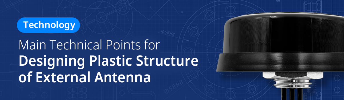
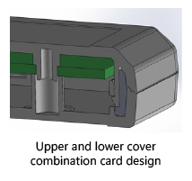
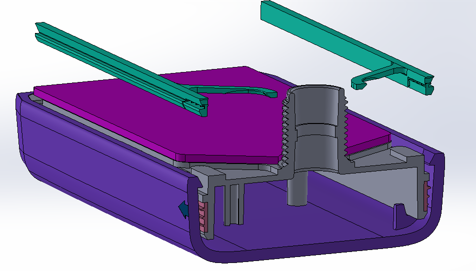
External antennas are often used in tough and strict environments such as vehicles, industrial machinery, and public transportation. The structure must ensure that the antenna module is stably positioned within the mechanism to prevent loosening or displacement due to vibrations, which could adversely affect signal quality. Standard securing methods include clips, screws, top and bottom cover locking, and foam compression. When designing, extra caution must be taken to avoid potential electromagnetic interference with the antenna.

- Avoid Metal Interference
In order to maintain frequency performance, metal materials should be avoided inside the plastic structure. If conductive materials are required due to structural strength or other requirements, the materials and positions should be coordinated with antenna engineers, and an electromagnetic interference assessment needs to be conducted in advance. When necessary, a metal shielding structure can be designed in directions that shall not radiate from the antenna to achieve a shielding effect.
- Reserved Antenna Radiation Space
It is recommended that the shell thickness does not exceed 2.5 mm to reduce the impact on antenna matching. If space permits, a safe gap of at least 5-10 mm should be maintained between the antenna and the plastic structure to ensure radiation efficiency.
II. Waterproof design: Structural details corresponding to IP rating requirements
- Waterproof Path and Sealing Design
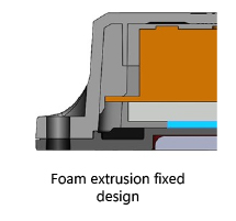
Common waterproof structures include silicone gaskets, liquid silicone filling and ultrasonic welding. It is recommended to choose the most suitable design method according to product requirements. A brief comparison is as follows:
| Design Approach | Advantages | Disadvantages |
| Silicone rubber gasket |
|
|
| Liquid Silicone |
|
|
| Ultrasonic Welding |
|
|
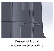
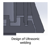
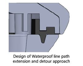
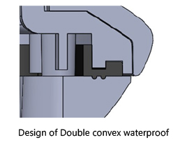
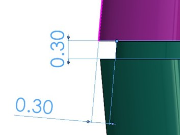
Furthermore, the waterproof line design should adopt the principle of stretching and bending to effectively extend the time for water pressure penetration and improve sealing reliability.
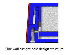
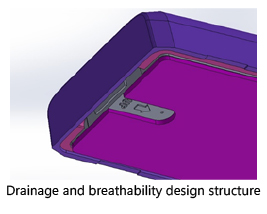
- Exhaust, drainage, and water guiding design
- The internal shell may experience thermal expansion and pressure accumulation due to a high-temperature environment. It is recommended to set up ventilation holes on the sides or bottom and attach a waterproof breathable membrane to maintain pressure balance and prevent deformation.
- Reserving drainage grooves or drainage holes at structural low points can effectively eliminate standing water, avoiding electrical leakage or material aging.
III. Convenience of Assembly Design: Balancing efficiency and reliability
1. Quick Assembly Structure
The upper and lower covers are often secured with screws, clips, ultrasonic welding, or spiral structures. Incorporating guide pillars and positioning structures can significantly improve assembly accuracy and reduce the risk of misassembling. Each approach has its own advantages and disadvantages as follows:
| Design Approach | Advantages | Disadvantages |
| Screw fastening | Higher strength, reworkable if needed | Longer working hours needed and costs, larger space required. |
| Clamping/Clips | Fast installation, lower cost | The mold is relatively complicated and not easy to take apart when needed |
| Ultrasonic welding | Lower cost, and great flexibility when it comes to design | Rework is not possible, quality is largely affected by stability of equipment. |
| Spiral structure | Operational intuition/ easy to operate, and reworkable if needed | High mold costs and the risk of shell cracking due to residual stress. |
- Reduce working hours and dependency on tools
- Reduce the number of structural components and avoid excessive reliance on screws and special tools.
- Introduce quick-release and screwless joint designs to improve production efficiency.
- Friendliness when it comes to Maintenance
Structural design should support module replacement to avoid the entire machine being scrapped due to antenna damage. Unictron has developed the “Hook-and-Strip Structure and Its Housing” technology to meet this need, which has obtained a patent (Announcement No: TW202410768A) and can serve as a demonstration for repair-friendly design.
IV. Appearance design requirements: Aesthetic and brand identification coexist.
- The design lines are consistent with the overall style of the device
- Adopts a streamlined, rounded design to avoid sharp protrusions, enhancing overall quality and safety.
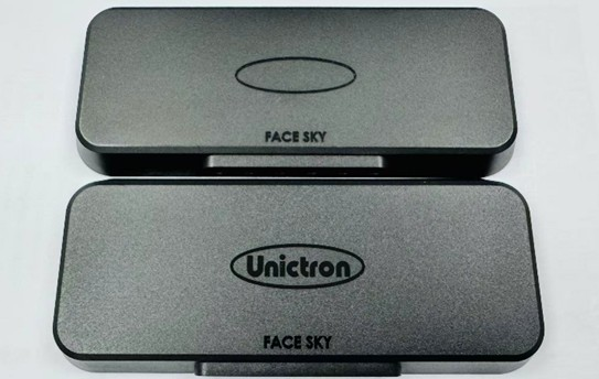
- It is recommended to design an indicative line at the junction of the top and bottom covers, which not only conceals the joint gap but also enhances the overall shape consistency.
- Surface treatment and visual texture
- It is recommended to use a matte finish on the surface to prevent fingerprints and scratches, with common standards like MT-11010, VDI-24, etc.
- Glossy surfaces can be treated according to SPI (Society of the Plastics Industry) standards, such as SPI-A2, SPI-A3, SPI-B3 specifications.
- It is advised to specify color numbers or fixed batches to avoid color differences affecting the quality impression.
- LOGO/Label Design Location
Reserve exclusive areas for branding, UV printing, or laser engraving applications to enhance product identification.
V. Material Design: Considering strength, radio frequency characteristics, and environmental resistance.
- Principles of Material Selection
- Plastic materials can affect antenna signal transmission, and when selecting materials, their dielectric constant (Dk) and dielectric loss (Df) should be reviewed:
| Material | Value of Dk | Applicable Scenarios |
| PP | ~2.2–2.5 | Low cost, suitable for short range detection applications |
| PC | ~2.9 | Good mechanical strength, moderate RF performance |
| ABS | ~2.8–3.0 | Commonly used for indoor products, with stable forming |
| LCP | ~3.0 with Df extremely low | High frequency, Millimeter wave applications |
| PPO | ~2.6 | Stability and heat resistance combined |
- For outdoor applications, it is recommended to use high weather-resistant materials such as PC, PC+ABS, ASA, PBT, etc., to withstand ultraviolet rays and to endure in harsh environments.
- Mechanical Performance Requirements
- High-strength areas may use GF reinforced materials (such as PA +30% glass fiber), but should still avoid antenna radiation areas.
- Assembly areas must have crack resistance feature and wear resistance, also must pass impact and pressure testing.
- Stable Formability and Tolerance
- Selecting high-flow materials can improve mold filling and snap-fit accuracy.
- For large-sized parts, it is suggested to control the shrinkage rate to less than 0.7% in order to minimize assembly tolerance errors.
The plastic structure design of the external antenna has evolved into a multi-tasking integration project that needs to carefully consider RF performance, environmental tolerance, structural strength and user experience. Through the design points summarized in this article, the development team can establish a standardized process and quality foundation; hence, improving product performance and brand image, and creating more professional and durable wireless products.